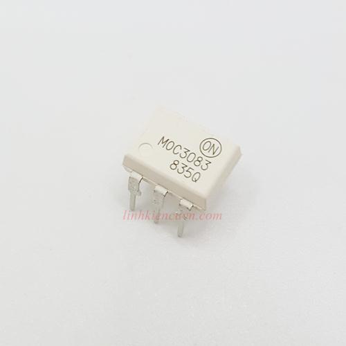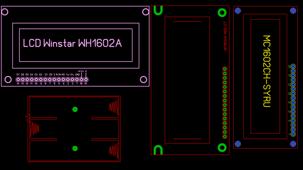

Furthermore, square and rectangular packages made it easier to route printed-circuit traces beneath the packages.Ī DIP is usually referred to as a DIP n, where n is the total number of pins. Increasingly complex circuits required more signal and power supply leads (as observed in Rent's rule) eventually microprocessors and similar complex devices required more leads than could be put on a DIP package, leading to development of higher-density chip carriers.


The dual-inline format was invented by Don Forbes, Rex Rice and Bryant Rogers at Fairchild R&D in 1964, when the restricted number of leads available on circular transistor-style packages became a limitation in the use of integrated circuits. The package may be through-hole mounted to a printed circuit board (PCB) or inserted in a socket. In microelectronics, a dual in-line package ( DIP or DIL), is an electronic component package with a rectangular housing and two parallel rows of electrical connecting pins.
#Dip 8 sprint layout download#
I think 2X50V is enough, even if you say I don’t want loud sound, it could be 2X30V 200W Amplifier Component ListĢX 6.8-OHM resistor – 1W (blue, gray, gold)ĤX 0.47-OHM 5W or 0.33-OHM 5W stone resistorġ0K – 1 / 4W resistor (brown, black, orange)įILE DOWNLOAD LINK LIST ( in TXT format): LINKS-27565a.8 contact DIP switch with 0.3" wide 16-pin (DIP-16N) footprint He says that it can be 2X62V DC, in this case the voltage of the capacitors used must be above 63V and instead of TIP41 TIP42 2SCC2073 (NPN) 2SA940 (PNP) or 2SA1837 (PNP) 2SC4793 (NPN) should be used. The 18K SMD resistor in the audio input has been changed to be DIP casing assembly.Finally, I removed the optional SMD filter capacitors, they were already staying away from the supply inputs, and the voltage input lines are very short and the roads are thick.įinally, when 2SC5200 and 2SA1943 are used for the writer output transistors (2SD1047 (NPN) 2SB817 (PNP)), the max. Note: I added the SMD option for 330PF in PCB Design, but removed it from the drawing to avoid confusion. If you are going to print PCB at home, do not select C1 when printing. I used C1 in the upper layer to strengthen the voltage inputs and outputs.

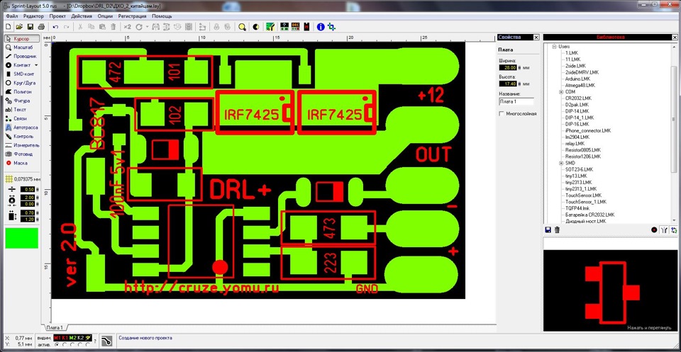
Printed circuit PCB dimensions are 100X49mm and single layer PCB drawing was made with Sprint Layout PCB program. instead I used 2 pieces of 56-OHM connected in parallel. The source of the circuit is reliable, and since the circuit was made by our readers before, I made the assembly of the materials and went directly to the test.I had a 2X30V transformer and 50W bass and 30W normal speaker cabinet.I could not raise the volume much more than 50% sound quality, power was very good 27-OHM 1W resistor I did not have. 200W Transistor Amplifier Circuit DiagramĢ00W Amplifier Test and Voltage Measurements The 5uH coil must be wide enough to pass into a 10-OHM 1W resistor to be wound 11 rounds of 1mm wire.
#Dip 8 sprint layout install#
The author said that a cooler can be used for TIP41-TIP42 transistors, but I left a hole for the cooler installation, but you can install 2 pieces of 2mm aluminum strip or a separate small cooler for all of them or you can look at the heat condition. 2N5401 can be used instead of 2SA1015, but the leg connections are different, be careful with this, the basin and collector legs should be changed in the PCB assembly (I have experimented with the 2SA733 transistors I have)ĢSC5200 and 2SA1943 transistors need to use insulators in the cooler assembly.You can look at the article Heat conduction and insulators for details, the equalization resistors of output transistors 0.33-OHM…. The 2SA1015 should show 180 or slightly less in the hFE measurement. To understand that the transistors are original, it is necessary to measure BETA or hFE with a digital multimeter. The author says about the 2SA1015 transistors that counterfeits are a lot on the market. If you cannot find a 330PF, you can use a 270PF capacitor instead. 2X50V DC 6A (2X33VAC or 2X36VAC transformers can be used) supply filter capacitors For usable bridge diodes between 4700uf… 10.000uf, ready KBU10M or 4 P600J 6 ampere diodes can be used.ģ30PF capacitor protects the amplifier from high frequency oscillations. The amplifier can deliver 100W RMS power with a 4-OHM speaker and a 200W RMS 8-OHM speaker.Īmplifier operating voltage max. The power transistors of the 200W Afi circuit do not require the classic 2SC5200 and 2SA1943 quiescent current adjustment. The single channel 200W version of the amplifier shared in the article 400w (2X200w) Transistor Amplifier Circuit was designed as small as possible in PCB size.


 0 kommentar(er)
